TEBAK
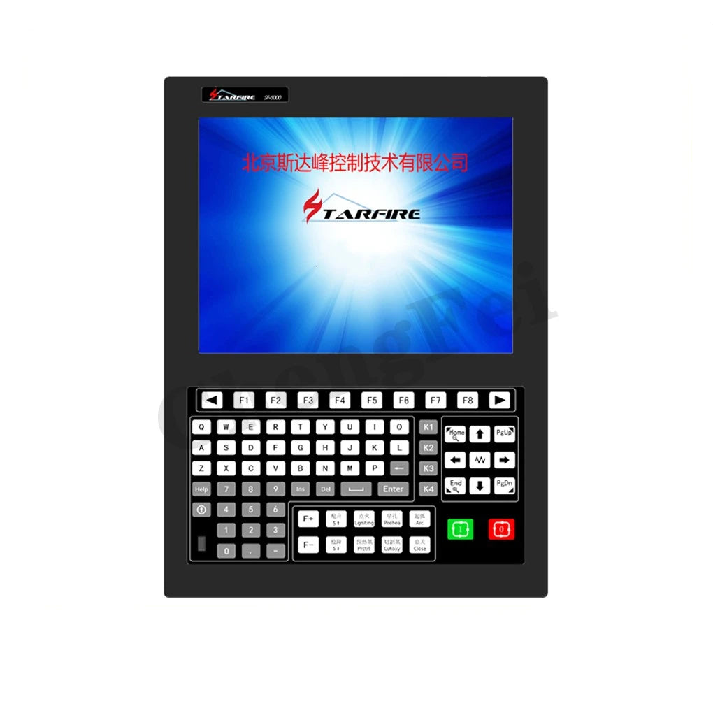
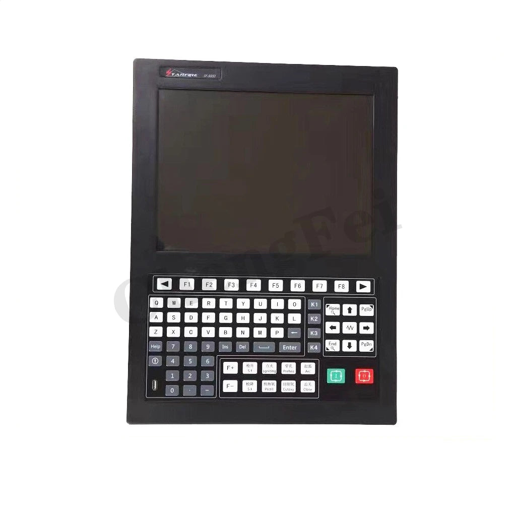
SF-5200S CNC plasma controller, 2-axis plasma cutting operating system, flame cutting motion controller
SF-5200S CNC plasma controller, 2-axis plasma cutting operating system, flame cutting motion controller
Couldn't load pickup availability
Product content:
1 × SF-5200S Plasma Controller
1 × 25-pin hole input plug (including sheath)
1 × 25 pin output plug (with sheath)
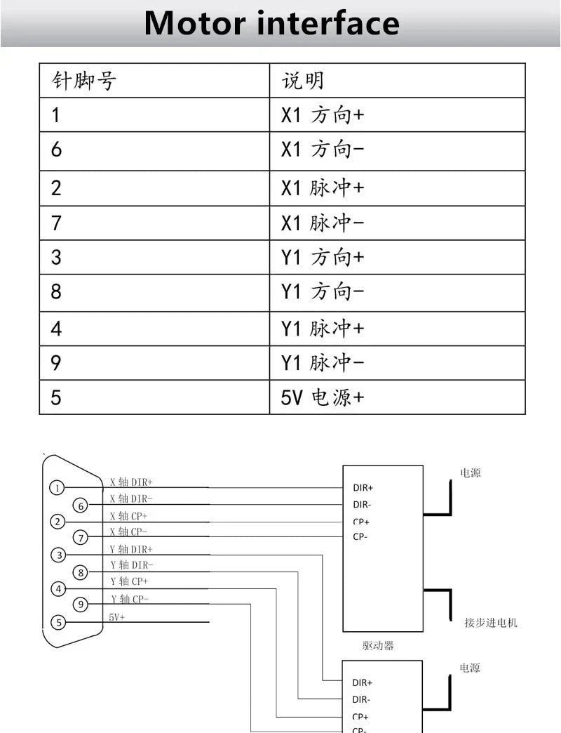
2 × two 9-pin motor plugs (including sheath)
2 × 9-pin hole plug two (including sheath)
1 × Power cable (AC22V standard cable)

Please read this manual carefully before using the system
Precautions for use:
1. After the packing box is opened, please check whether the system is damaged during transportation, and whether the contents listed on the packing list are consistent with the contents in the box.
2. This manual is applicable to the SF-5200S-QG CNC cutting machine system produced by Beijing Star Peak Control Technology Co., Ltd.
3. Please check whether the grid voltage is correct. An isolation transformer of AC220V should be used between the power grid and the system to ensure the reliable operation of the system and the safety of personnel.
4. The numerical control system requires the working environment temperature to be 0℃~+40℃, and the relative humidity to be 0~85%.
Such as working in high temperature, high humidity and corrosive gas environment, need to take special protection.
5. The wiring of each part of the CNC system should be correctly connected as required, and the ground wire should be in good contact.
6. The numerical control system does not allow plugging and unplugging of all cable plugs at the rear of the chassis with power on, and the company refuses to guarantee the resulting consequences.
7. The line of the output port at the rear of the CNC system is not allowed to be short-circuited with other power lines, otherwise the CNC will be burned.
8. In a high dust environment, the whole machine needs to be protected from dust, and dust needs to be cleaned regularly to ensure the cleanliness of the CNC system as much as possible.
9. The numerical control system should be managed by special personnel, and relevant training should be given to the operators.
10. It is not allowed to connect the AC/DC power supply used inside the CNC system to other external electrical appliances.
11. If you have any questions, please contact our company. Do not disassemble or modify the system by yourself under unfamiliar conditions.
12. To maintain the system and machine tools, perform routine maintenance and inspection once per shift; perform secondary maintenance once a month; perform primary maintenance every six months.
13. The parameters set by the numerical control system must be set in strict accordance with this manual or the supplementary instructions when ordering; if the set parameters exceed the specified range, the numerical control system may work abnormally or even be damaged.
14. The LCD screen of the system is a fragile item. Pay attention to the protection of the LCD during use.
15. The technical indicators of this system are subject to change without prior notice.
16. Note: The output power of the USB port of the system is very small, which can only be used for U disk, and cannot be connected to other USB devices to prevent damage.
17. Special statement: The warranty period and warranty scope of this product is within 12 months from the date of delivery, and the failure occurs under the conditions permitted by the instructions for use. The processing of failures outside the warranty period and outside the warranty scope is a fee-based service.
The following situations are not covered by the warranty:
A: Man-made damage in violation of the use requirements;
B: Damage caused by force majeure;
Force majeure usually includes two situations:
One: caused by natural causes, such as lightning strikes, floods, droughts, snowstorms, earthquakes, etc.;
The other: caused by social reasons, such as wars, strikes, government bans, etc.;
C: Damage caused by unauthorized disassembly, modification, repair, etc. without permission.
System functions:
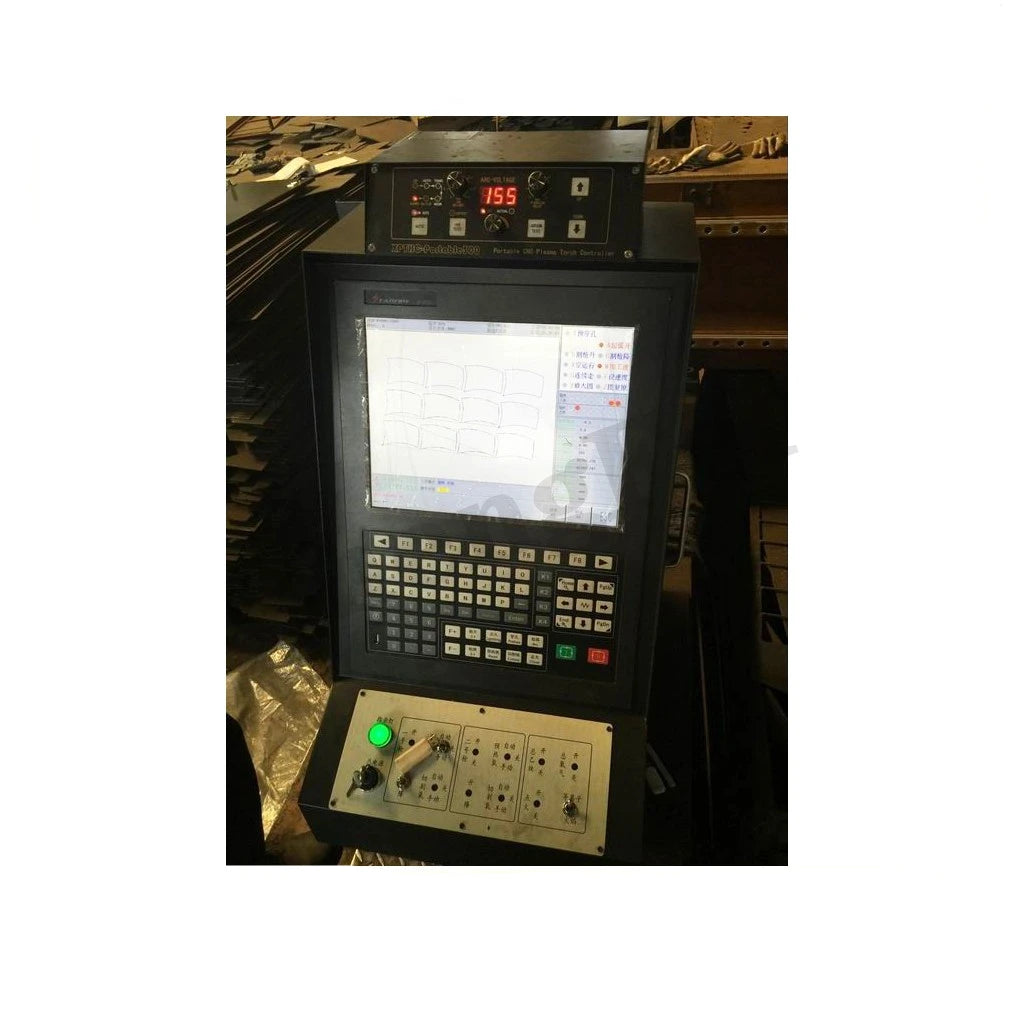
SF-5200S-QG CNC cutting machine system can control the machine tool to do flame or plasma cutting. It can be set through process selection (parameter setting, see Chapter 7 for details). The operation and display of the system are prompted by step-by-step function windows. Example: In the main window menu, after calling a function, the system will launch the function's sub-window menu. According to the prompt of the screen window, press [F1] to [F8] to select the corresponding function, and press [ESC] to return to the previous menu.
System Features:
◆ SF-5200S-QG cutting machine CNC system is suitable for all kinds of flame/plasma, high pressure water jet, laser cutting machine, widely used in metal processing, advertising, stone and other industries.
◆ The system is designed with high reliability and has the ability to resist plasma interference, lightning strike and surge.
◆ Practical flame/plasma cutting process, automatic control of corner speed and height controller during plasma processing.
◆ Remote operation can be realized by wireless remote control or wired hand control box.
◆ It has the function of kerf compensation, and detects whether the compensation in the program is reasonable, and makes corresponding reports for users to choose.
◆ Breakpoint recovery, automatic power failure recovery function, automatic breakpoint memory.
◆ Optional segment selection and perforation point selection processing function, can skip processing at will during processing.
◆ It has the function of epitaxial perforation suitable for thick plates, and the function of bridging suitable for thin plates.
◆ Functions such as rollback, section selection, breakpoint recovery, and optional perforation position are available, which are very convenient for users to control.
◆ You can transfer and cut at any time, choose the starting point for processing, and automatically generate broken bridges during processing.
◆ It adopts special small line segment processing function, which makes it walk smoothly and can be widely used in metal blanking, advertisement, iron art, etc.
◆ Parts library with 24 kinds of graphics (expandable), including common basic machining parts.
◆ Fully compatible with STARCAM nesting software, and also compatible with mainstream nesting software such as IBE (Germany) and FASTCAM.
◆ Chinese and English operation interface conversion, dynamic graphic display, 1-8 times graphic magnification, automatic tracking of moving points.
◆ Multi-language operation interface conversion, such as Chinese, English, Russian, German and so on.
◆Using U disk reading program and timely software upgrade.
◆ Support boot LOGO picture customization, users can modify it by themselves.
◆ Upgrade button front, easy to operate.
Hardware Specifications:
◆ Adopt industrial grade ARM processing chip;
◆ Adopt 15-inch true color TFT display, resolution 1024*768;
◆ The system provides 16 channels of photoelectric isolation input and 14 channels of photoelectric isolation output.
◆ Number of linkage axes: 2 axes, (two X axes; two Y axes; bilateral drive is possible).
◆ Pulse equivalent: electronic gear numerator, denominator setting range﹙1~65535﹚.
◆ The running memory is 64M, which can process super large processing programs.
◆ User program storage space: 2G~4G (SF-5200H).
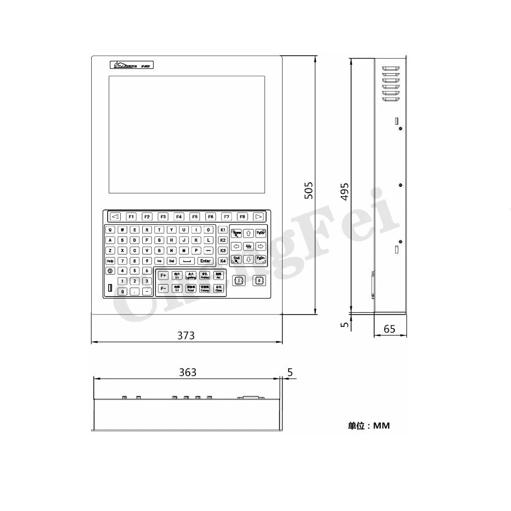
◆ Chassis size: 410 × 310 × 119 (mm);
◆ Working temperature 0℃~+40℃;
◆ Storage temperature -40℃~+60℃;
Function word definition:
◆N instruction segment number
◆ G-ready function
◆M auxiliary function
◆T tool function (refers to flame width in this system)
◆ L cycle times, delay time
◆X X axis (diameter) absolute coordinates
◆Y Y axis absolute coordinates
◆ During I arc processing, the coordinate value of the center of the circle minus the starting point value of the X axis
◆J During arc processing, the coordinate value of the center of the circle minus the starting point value of the Y axis
◆R Arc radius specification
◆H arc chord height specification
◆A auxiliary variable
◆F Machining speed designation, used for G01, G02, G03
Parameter Description:
◆l Speed parameter
◆l Starting speed, adjustment time and maximum speed limit of each axis;
◆l System parameters
l Electronic gear ratio of each axis, machine origin, reference point, backlash, line drawing offset, soft positive/negative limit;
◆l Flame cutting parameters
l Ignition delay, preheat delay, torch up/down delay, perforation torch up/down, perforation delay, etc.;
◆l Plasma parameters
◆l Torch positioning delay, M command for arc starting, M command for arc breaking, arc voltage detection selection, positioning detection selection, perforation delay;
◆l Control parameters
◆l Flame/plasma mode selection, processing speed limit, edge perforation selection, metric/imperial selection, etc.;
◆l Storage function
◆l Store the modified parameters in the parameter area.
◆l Press the S key continuously to select the external manual control key, which can be manually enabled or disabled.
◆Software upgrade operation instructions (software upgrade free of charge)
Operation steps
◆1. First format the U disk with FAT or FAT32 format, it is recommended to use FAT format.
◆2. Copy the upgrade file to the U disk, the name of the upgrade file must be STARTCNC.EXE .
◆3. Press and hold the arrow button on the left side of the USB port, turn on the system power, power on the system, and insert the U disk into the USB port of the system;
◆4. The system automatically enters the upgrade interface, press the F1 key on the panel (that is, the key corresponding to the upgrade);
◆5. If the upgrade is normal, after the upgrade is completed, the system will display "Upgrade Successful!".
◆ 6. Turn off the power, pull out the U disk, and the upgrade process is complete.
Handling of exceptions in the upgrade process:
The name of the check upgrade file must be STARTCNC.EXE .
If this factor has been ruled out, you can re-operate according to the operation steps. If you still fail after several attempts, you can call the customer service staff.