TEBAK
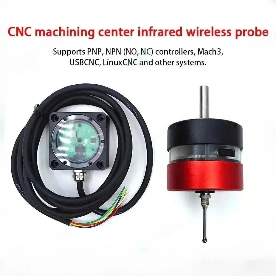
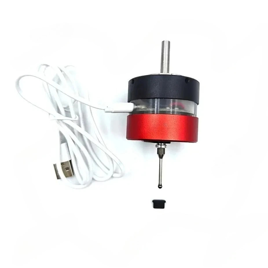
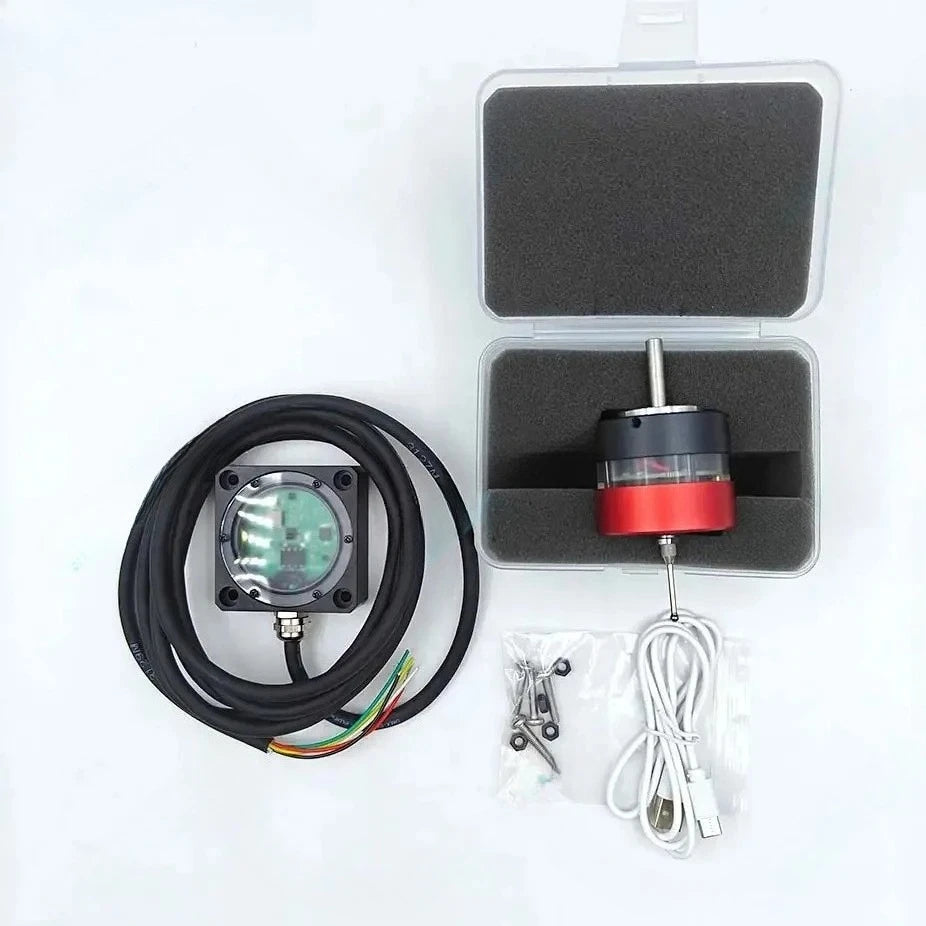
CNC wireless touch probe 3d edge finder machining center CNC milling machine three-coordinate probe centering tool setting Mach3
CNC wireless touch probe 3d edge finder machining center CNC milling machine three-coordinate probe centering tool setting Mach3
Couldn't load pickup availability
CNC wireless probe is suitable for LinuxCNC, Mach3 edge finder and machining center. Most control systems have three-coordinate edge finding, centering and tool setting.
Instructions for use:
Probe screen v2 master for LinuxCNC

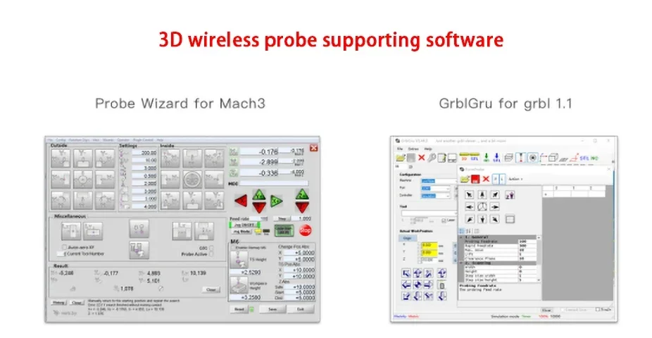
If it is a Mach3 system, it is recommended to use the free and open source Probe Wizard. After purchasing, ask customer service for the software package.
If it is an engraving machine with grbI control board, it is recommended to use free GrblGru, download address: http://www.grblgru.com/
Instructions for use:
1: Use the Type-c interface to charge. It can output 5V 1A for both fast and slow charging. It takes about an hour to fully charge (please do not use the Type-C cable, as different definitions may cause damage). The indicator light is red when charging, and the indicator light is green when fully charged.
2: The normal indicator light is green when the measurement is triggered. When the battery voltage is lower than 2.9V, the trigger indicator light will turn into a red indicator light to remind you that it needs to be charged. (The red indicator light can probably be used for about 3~4 days and needs to be charged as soon as possible).
3: Do not turn on the spindle rotation when using the probe, as it may cause damage to the probe.
4: Receiver 5-core signal output line, respectively powered by 5~24V+ (red) GND (black) COM (white) NC (green) NO (yellow), supports NPN and PNP normally open or normally closed modes.
Among them, V+ can be connected to the power supply interface in the 5~24V range on the system. There is no requirement for the operating current, only 50ma COM according to the probe signal input method supported by the system.

When the system is NPN, COM is connected to the system signal GND, and the system probe input signal is connected to NC or NO according to normally open or normally closed.
When the system is PNP, COM is connected to the system signal VCC, and the system probe input signal is connected to NC or NO according to normally open or normally closed.
In general, if the system supports it, it is recommended to use NC normally closed wiring, which has a relatively shorter delay.
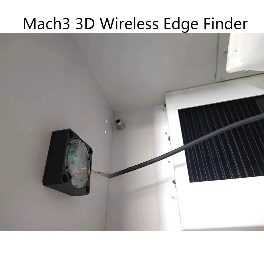
5: Receiver installation requirements. The receiver is generally installed on the side or top of the machine in an unobstructed area. It can be temporarily fixed using the magnetic suction on the back, and then the hand-held probe is pressed and triggered to test whether it can be received normally within the range of the travel (when receiving a signal, the receiver The red light is on), determine the appropriate installation position and drill holes to install M4 fixing screws.
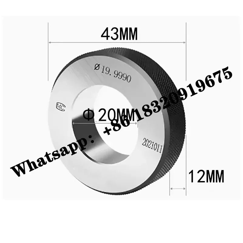
6: The concentricity of the probe will be adjusted to within 0.05 before shipment (because of transportation vibration, even if it is adjusted to 0.01, the original accuracy cannot be guaranteed after receiving the goods), and it needs to be adjusted to 0.01 after receiving the goods.

|
Measurement direction |
+X, +Y, +Z |
|
|
Safe measurement of travel |
XY plane +20°. +2.5mm in Z direction |
|
|
One-way repeatability |
<0.01mm |
|
|
charging method |
Type-C interface 5V-1A |
|
|
Charging time |
1 hour |
|
|
battery capacity |
900mah lithium battery |
|
|
stand-by current |
0.13ma |
|
|
Standby time |
3 with |
|
|
length of work |
1~2 months |
|
|
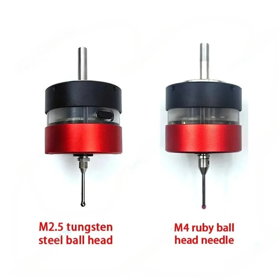
Probe interface |
M2.5 |
|
|
Sealing level |
Dustproof and waterproof IP54 (splashproof, cannot be soaked) |
|
|
weight |
160g |
|
|
Operating Voltage |
5-24V DC |
|
|
Working current |
50ma |
|
|
Signal mode |
NPN PNP NC NO fully supported |
|
|
a fixed way |
Fix with M4 screws or magnetically attached to the back |
|
|
Signal line length |
3m |
|
|
Receiving distance |
2m |
|
|
weight |
180g |
|
 |
serial number |
name |
Material |
||
|
1 |
6MM clamping handle |
Stainless steel |
|||
|
2 |
Seal 1 |
rubber |
|||
|
3 |
M3 adjustment |
carbon steel |
|||
|
4 |
back cover |
aluminum |
|||
|
5 |
Seal 2 |
rubber |
|||
|
6 |
Lithium battery |
||||
|
7 |
Acrylic middle frame |
Acrylic |
|||
|
8 |
Seal ring 3 |
rubber |
|||
|
9 |
Main control circuit |
Printed |
|||
|
10 |
gold plated contact |
Printed |
|||
|
11 |
The front cover |
aluminum |
|||
|
12 |
tripod |
Stainless steel |
|||
|
13 |
Silicone dust cover |
Silica gel |
|||
|
14 |
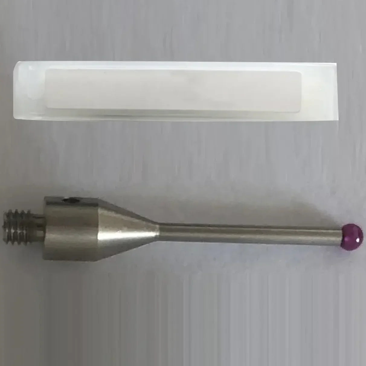
M2.5 stylus |
Tungsten |
|||